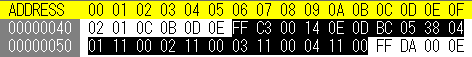
The 2 byte value (0xFF 0xC3) in address 0x0000 0046 is SOF3 Marker.
The 2 byte value (0x00 0x14) in address 0x0000 0048 is the segment length (Lf). In the sample, Lf is 20 byte. This length includes itself.
The 1 byte value (0x0E) in address 0x0000 004A is the sample precision (P). In the sample, this value is 14 bit.
The 2 byte value (0x0D 0xBC) in address 0x0000 004B is the number of lines (Y). In the sample, this value is 0x0DBC = 3516.
The 2 byte value (0x05 0x38) in address 0x0000 004D is the number of samples per line (X). In the sample, this value is 0x0538 = 1336.
The 1 byte value (0x04) in address 0x0000 004F is the number of image components in frame (Nf). In the sample, this value is 4.
Now, (X) x (Nf) must equal the Sensor Width.
From address 0x0000 0050 , information for each image component is stored per 3 byte length.
The 1 byte value (0x01) in address 0x0000 0050 is the component identifier (Ci).
The high 4 bit of 1 byte value (0x11) in address 0x0000 0051 is the horizontal sampling factor (Hi).
The low 4 bit of this byte value is the vertical sampling factor (Vi).
Perhaps, Hi and Vi are always 1 in CR2 format, I think.
The 1 byte value (0x00) in address 0x0000 0052 is the quantization table destination selector (Qi).
This value is always 0 in Lossless mode.
Other image component information is stored in following address in the same way.
4.4 SOS - Start Of Scan
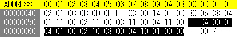
The 2 byte value (0xFF 0xDA) in address 0x0000 005C is SOS Marker.
The 2 byte value (0x00 0x0E) in address 0x0000 005E is the scan header length (Ls). In ths sample, Lf is 14 byte. This length includes itself.
The 1 byte value (0x04) in address 0x0000 0060 is the number of image components in scan (Ns).
In the sample, this value is 4.
From address 0x0000 0061 , information for each image component in scan is stored per 2 byte length.
The 1 byte value (0x01) in address 0x0000 0061 is the scan component selector (Cj).
The high 4 bit of 1 byte value (0x00) in address 0x0000 0062
is the DC entropy coding table destination selector (Tdj).
The low 4 bit of this byte value is the AC entropy coding table destination selector (Taj). In Lossless, this value is always 0.
In the end, #1 and #3 image component use #0 DC entropy coding table (Huffman table), #2 and #4 image component use #1 DC entropy coding table (Huffman table) in the sample..
The 1 byte value (0x01) in address 0x0000 0069 is the predictor selection (Ss).
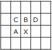
The algorithm is selected for each Ss value as follows:
Ss value
Algorithm (Predict X)
0
No predict
1
A
2
B
3
C
4
A+B-C
5
A+(B-C)/2
6
B+(A-C)/2
7
(A+B)/2
Perhaps, Ss is always 1 in CR2 format, I think.
The 1 byte value (0x00) in address 0x0000 006A is the end of spectral selection. This value is always 0 in Lossless.
The high 4 bit of 1 byte value (0x00) in address 0x0000 006B
is the Successive approximation bit position high (Ah). In Lossless, this value is always 0.
The low 4 bit of this byte value is the point transform (Al).
In the sample, this value is 0 ,and we do not need consideration.